Back To Front Page |
|
TA-312/PT TA-43/PT Diagnostics
Back to Tech Info
Note: Offered here are some common operational problems with the TA-312/PT TA-43/PT. I recommend that old proven adage acronym: "KISS," then progressively and methodically perform some of the following procedures as I suggest here, through the benefit of experience; also some consulting with the tech manuals -- so, it is not always a "winging it," close your eyes, cross your fingers, and hope it works procedure -- sometimes spitting on it or whacking it works also.
By all means if you have additional and/or a better method of diagnostics you would like to contribute to this site, please e-mail me; I would greatly appreciate it.
Common Problems with these Field Telephones:
I will continue to add more problematic symptoms and corrections as I have time
Definition: "Sidetone." This is a common diagnostic check. When you blow in the H-60/PT Handset's transmitter, with the Push-To-Talk switch depressed, one should hear the blowing sound clearly in the handset's receiver. Of course the ultimate test is being able to talk with a connected remote field telephone. If that fails, it could be a defective Hook Switch -- with the H-60/PT off the cradle/hookswitch, check to see that the four contacts should be closed at the copper hookswitch.
Isolation by substitution: Best method, if you are fortunate enough to have more than one field telephone, try substituting known good like-components for suspicious defective ones and testing it again -- works everytime. Not everyone has that luxury though.
- I can't get sidetone
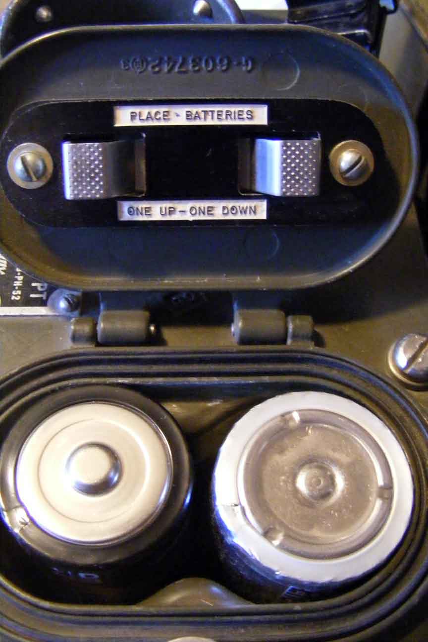
- Correction: Check Battery's UP/DOWN orientation in the battery compartment. I can't believe how many times I have made the mistake of hastily inserting batteries incorrectly:
- Still doesn't work, after batterie's UP/DOWN orientation is verified.
- No reception -- but Xmtr works. Remember, the receiver circuit by-passes the Push-to-talk switch. Assuming you are using a known good TA-235 Rec Element, check the electrical continuity of the Blue and Yellow wires from the Rec End leading into the Xmtr cavity end. And/or jumper the Blue and Yellow contacts on the TA-235 directly to the Varistor in the Xmtr cavity where the Existing Blue and Yellow wires are. Once jumpered, you can check the reception by holding the jumper TA-235 t0 your ear. Often these two wires get twisted around and break inside the insulation with no exterior break visible.
If that's the problem, simply substitute two short wires for the Blue and Yellow wires -- pull out the wires from the receiver end and insert/slip two good wires through the body of the handset to the receiver end. Radio Shack has short jumper wires or make your own. This was my problem, twice in one week, when I was fixing a couple of phones -- had me "baffled" because I couldn't see any visible damage on the blue or yellow wires. See Receiver Problems
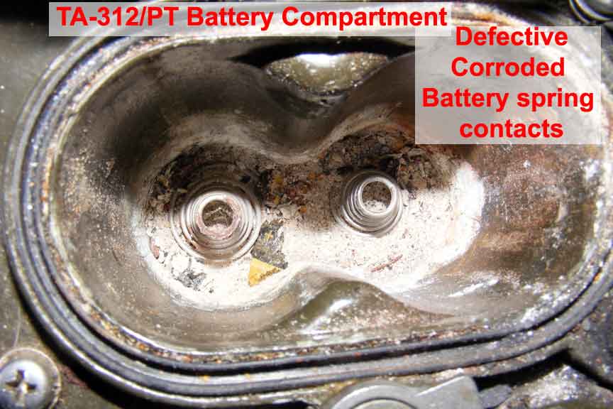
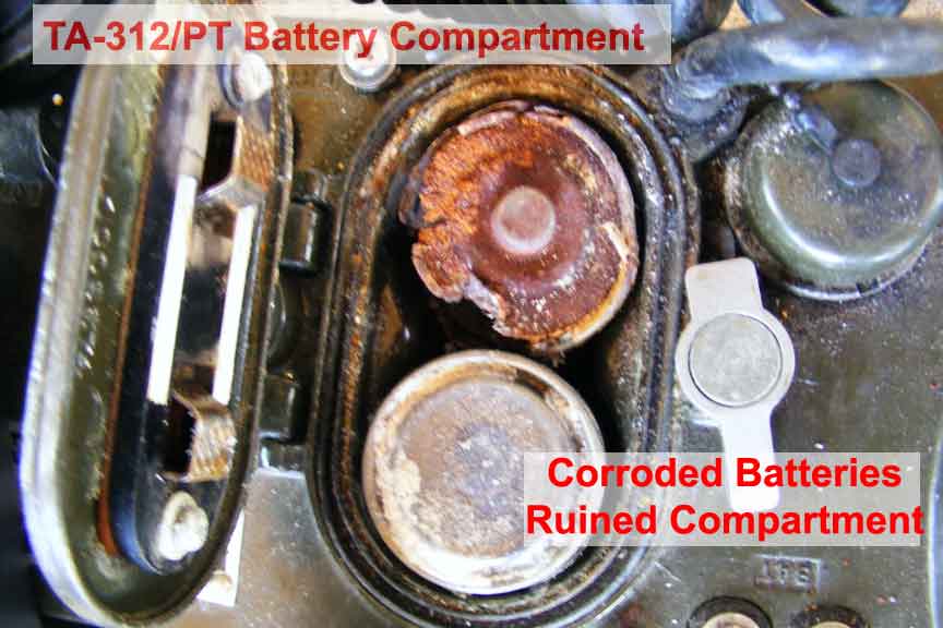
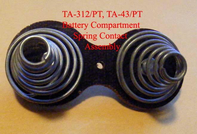
- Correction: Inspect the bottom of battery compartment's spring contact assembly for corrosion and/or rust residue; if some is present, significant battery power attenuation or voltage resistance will decrease the operational effectiveness: The point here is of course -- never leave batteries in the battey compartment for an extended period. Battery acid leakage can occur. When battery acid is present clean the contacts with a fine sand paper grade and/or electrical contact liquid. If replacement of the spring contact assembly is necessary, I do carry these new contact assemblies:
Note: As my personal anecdote of battery acid leakage damage shown above as indicated in a previous page where I recommended "Duracell" because of the absence of battery leakage after 20 years of storage without battery leakage.
- Correction: Check Push-To-Talk Switch: Sometime this SA-129/PT switch is intermittent and sometimes it's just plain defective. There are one of two types of switches that can be found in these H-60/PT handsets:
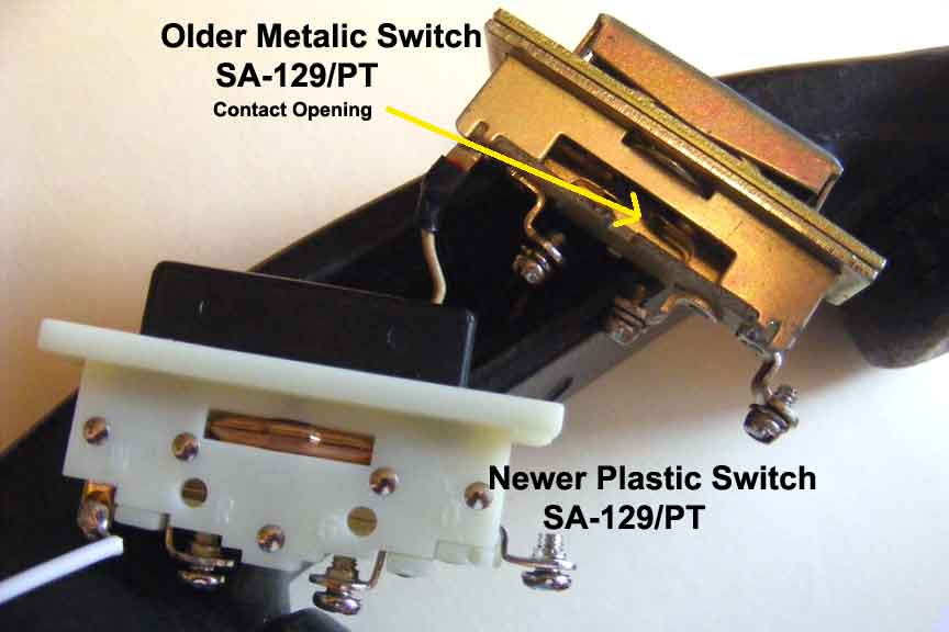
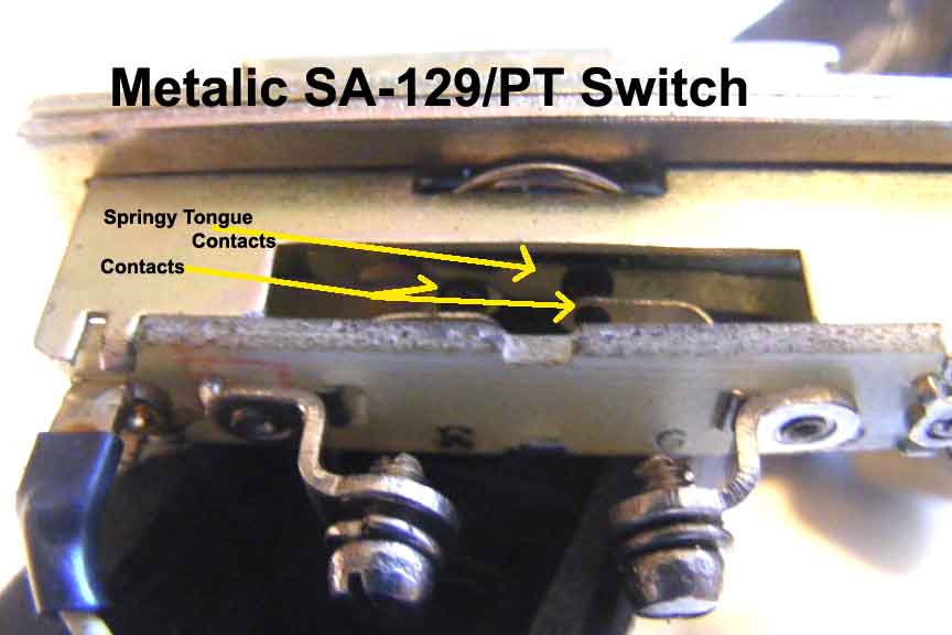
The older, original metallic switches with an small aperture on the side allow access to the spring contact elements, and the newer, second type is the completely enclosed white plastic switch, with no access to the contact elements.
The metallic one can usually be fixed by rubbing a sand-paper nail file between the contact elements to clean them and gently pulling on the wafer-thin tongue contacts to reset the resiliency of the springy characteristics.
If you have a defective white plastic switch, it's just best to replace it. Usually these switches gradually become defective, becoming intermittent to finally stop working. Think about it: this switch is probably the most manipulated component of the field telephone, besides the fact that these field telephones are over 50 years old.
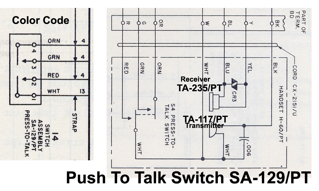
- Can't Transmit; and only hear a clicking sound at the remote connected field telephone: . Check for a defective Push-To-Talk switch SA-129/PT; look at the the wire and color code diagram depicted above and perform continuity tests with an omh meter in the "closed" and "open" positions at the contacts 1 through 4.
- Replace missing, dry-rotted, or torn rubber switch protective covers. Dirt, dust, and moisture can be a major problem with malfunctioning telephones. This can prevent intermittent headaches.
- Replacing the CX-2151/U Electrical Cord Assembly on a Handset: For what it
is worth.
To replace the cord/coil I would suggest to pat/rub a little WD-40 lightly
on the cable insertion ends to facilitate squeezing them in the small
aperture on the telephone H-60 handset and the housing unit.
If the old cable has no reusable value, I just snip them off at the entry
hole and pull them out from the inside -- they come out easier.
If you are exchanging an existing one, just follow the existing connections
from the old one - further guidelines follow. In the event you are
replacing a coil/cord that was previously removed, here are some guidelines:
Follow the color code markings on the black terminal board in the housing
and on the handset H-60's push-to-talk switch for the three wires leading
out from Transmitter end-and coil/cord. Notice on one end that the blue and
yellow wires are shorter and that the Red, Orange and Green wires on the
same end of the cord are longer -- use this end for the Transmitter end of
the H-60 handset. This is the Red wire that has a black extended ¼ inch
insulation covering. Those three longer wires will be connected to the
Push-To-Talk Switch, as you will see when you disassemble it. If you have an
easier method, by all means please let me know. Through many mistakes I
finally have this procedure right, attentive to following the color code
etched on the side of the switch -- Orange, Green and Red with the extended
¼ black tape insulation at the open-end connector.
The handset coil end anchor screw just needs loosening to slide out the
anchor hook-not necessary to remove. Also, It isn't necessary to remove the
two other tiny screws in the transmitter end to extract or replace the
cable. Here's why: the two existing bottom yellow and blue wires at the
handset transmitter end are closed loop connectors -- these remain on the
bottom under the screw. the upper second set of yellow and blue wires from
the coil/cord are open-end connectors and these wires can just be slid out
when the screw is loosened, as well as the new wires can be slid on. I
mention this because it's "hell" putting those tiny,tiny screws back on --
so don't remove them; just loosen them. However, if you inadvertently
unscrew off the screws then it is necessary to adroitly manipulate and
painstakingly navigate these very tiny screws in place; because occasionally
I do completely unscrew them I finally purchased a clutch/screw driver with
the holding screw clutching fingers -- so much easier and significantly
faster to screw in those tiny, tiny screws in tight places.
I carry new SA-129/PT Rubber Switch Covers and SA-129/PT switches for $7.95, and $9.95 respectively, and $2.90 shipping See my Parts/Replacement see list page: Parts List Page

Back To Front Page |
|

